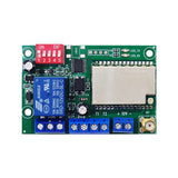
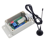
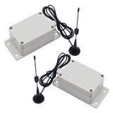
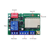
Note: This synch module requires two or more to be used together.
Package Include:
1 x Bidirectional Synchronous Module: SM002-1D-5000
1 x User manual
Product introduction
The wireless remote synchronization module is a bi-directional wireless device with integrated transmit and receive functions. It is a terminal device that realizes remote transmission of switch values through LoRa modulation technology. It supports the collection of switch input and control relay output. The core of its function is to realize remote synchronous control without wiring. It is highly usable and convenient for users to quickly integrate into their own systems.
Application
It has a 12V DC voltage output, a dry relay output and two trigger terminals.
Two or more synchronization modules can form a wireless synchronized remote control system. Any module in the system can be used as the transmitter or the receiver. All modules in the system will be automatically synchronized to maintain the same state.
It can long range remote control DC AC equipments, such as light, lamp, electric lock, motor, pump, fan, solenoid valve, socket, outlet, heater, etc.
Feature
Wireless control, easy to install.
Waterproof: The synchronous module has waterproof case and waterproof connector, and it can be installed outdoors.
Triggered By Normally Open Dry Contact.
With a 12V DC Voltage output and a dry relay output.
The relay output terminals are NO / NC (normally open / normally closed), serving as a switch.
Have a 5-position DIP switch, First, second, third positions are used for channel selection (8 channel combinations), fourth position is used for working mode selection, and fifth position is used for repeater function activation.
The synchronous module can trigger another synchronous module from any place within a reliable working distance.
The wireless RF signal from the synchronous module can pass through walls, floors, doors, or windows, but it will lose some operating range.
The synchronous module can only be triggered by other synchronous modules with the same channel.
Two or more sets of synchronized modules with different channels can be used in the same area, they will not interfere with each other.
Switch Parameters
Model: SM002-1D-5000
Operating Voltage: 12V DC
Working Frequency: 420MHz
Emission Current: 120mA
Relay Contact Current: Max 10A
Output 1: 12V DC Voltage
Output 2: Relay Output (With Normally Open and Normally Closed Terminals)
Suitable Wires for Connecting Terminals: 22-16 AWG
2 Selectable Working Modes: Self-locking, Momentary
Transmission Distance: 5 km / 3 mi (theoretically)
Operating Temperature: -20 °C ~ +70 °C
IP rating: IP65
PCB size: 69 x 39 x 17 mm
Case size: 138 x 68 x 50 mm
Working Range:
Two synchronous modules can form a complete set, and the maximum working distance can reach 15000 feet (5000 meters) in an open area.
The maximum working distance is a theoretical data, it shall be operated in an open ground, no barriers, no interference. But in the practice, it will be hindered by trees, walls, or other construction, and will be interfered by other wireless signals. Therefore, the actual working distance may not reach this maximum distance.
Usage:
The synchronous module can be used to control DC 0~28V or AC 110~240V devices.
Notice: Initial state of relay output terminals: Terminals <NO> and <COM> are Normally Open; Terminals <NC> and <COM> are Normally Closed.
Wiring:
Connect the 12V DC power supply:
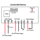
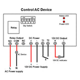
Connect the positive pole of 12V DC power supply to terminal <POW +> of the synchronous module, and connect the negative pole of 12V DC power supply to terminal <POW -> of the synchronous module.
1) If you want to connect a 12V DC indicator to the module, do as following:
Connect terminal <+> of 12V DC output to the positive pole of the indicator, and connect terminal <-> of 12V DC output to the negative pole of the indicator.
2) If you want to connect a DC device to the module, do as following:
Connect terminal <NO> of the relay output to the positive pole of DC power supply, connect terminal <COM> of the relay output to the positive pole of DC device, and connect the negative pole of DC device to the negative pole of DC power supply.
3) If you want to connect an AC device to the module, do as following:
Connect terminal <NO> of the relay output to the live wire of AC power supply, connect terminal <COM> of the relay output to one side of AC device, and connect another side of AC device to the neutral wire of AC power supply.
How to set up the same channel
If you want to set up several synchronization modules to work together, you need to set the positions 1-3 on the DIP switch of all synchronous modules to the same position, and it can have 8 different combinations.
| Combination of 8 different channels | |
| 1 | Position 1 to OFF, Position 2 to OFF, and Position 3 to OFF |
| 2 | Position 1 to OFF, Position 2 to OFF, and Position 3 to ON |
| 3 | Position 1 to OFF, Position 2 to ON, and Position 3 to OFF |
| 4 | Position 1 to OFF, Position 2 to ON, and Position 3 to ON |
| 5 | Position 1 to ON, Position 2 to OFF, and Position 3 to OFF |
| 6 | Position 1 to ON, Position 2 to OFF, and Position 3 to ON |
| 7 | Position 1 to ON, Position 2 to ON, and Position 3 to OFF |
| 8 | Position 1 to ON, Position 2 to ON, and Position 3 to ON |
How to set different working modes (Modules on the same channel)
1) Setting Self-locking mode: Set the fourth position on the DIP switch to ON.
The operation of Self-locking mode:
Connect the T1 and T2 terminals of a synchronous module, all modules will output 12V DC voltage, and all module relay outputs will be activated. All devices connected to the modules will be turned on.
Connect the T1 and T2 terminals of this synchronous module again, all modules will stop to output 12V DC voltage, and all module relay outputs will be disactivated. All devices connected to the modules will be turned off.
2) Setting Momentary mode: Set the fourth position on the DIP switch to OFF.
The operation of Momentary mode:
Connect the T1 and T2 terminals of a synchronous module, all modules will output 12V DC voltage, and all module relay outputs will be activated. All devices connected to the modules will be turned on.
Disconnect the T1 and T2 terminals of this synchronous module, all modules will stop to output 12V DC voltage, and all module relay outputs will be disactivated. All devices connected to the modules will be turned off.
How to turn on the repeater function (Modules on the same channel)
When the distance between two synchronous modules is too far and wireless signal cannot be transmitted smoothly, you can install another synchronous module between these two synchronous modules and turn on its repeater function.
If you want to turn on the repeater function of the synchronous module, you need to set the fifth position on the DIP switch of this synchronous module to ON.
Work process: When this synchronous module receives a wireless signal from another module, it will be triggered and retransmit this wireless signal at the same time.


