


Product Application:
It is suitable for a variety of automation occasions, such as industrial, agricultural, commercial and home intelligence. Through smartphones and the Internet, we use this WiFi switch to achieve remote control of various devices such as electric curtains, small bi-directional DC motors (two control lines), small bi-directional AC motors (three control lines), linear actuators, etc.
Product Parameters:
Working voltage: DC 6~24V
Output: relay output (normally open and normally closed)
Relay working voltage range: AC 110~240V or DC 0~28V
The range of wires that the terminals can be connected: 22-12 AWG
Channel: 3 Channels
Working mode: Interlocking (CH 1 and CH 2), Self-locking (CH 3)
Static current: ≤6mA
Working temperature: -20°C ~ +70°C
Maximum load: 10A/channel
PCB size: 93x45x19mm
Shell size: 115x90x42 mm
Product Features:
Connect to the Internet via the WIFI signal of the wireless router.
Via smartphone app to control, no distance limit.
Relay output: The output terminal is NO / NC and can be used to control DC or AC equipments.
Manual switch port: Can be connected tomanual switches or other devices to control the WiFi switch.
Limited switch port: Can be connected to limit switches or other devices to control the WiFi switch.
It has the characteristics of reverse power protection and overcurrent protection.
It offers APP for Android or iOS, and APP is free to use.
The Android version of the app supports a variety of Android phones or tablets.
The iOS version of the app supports a variety of iPhone, iPad and iPod Touch.
The APP supports English, French, German, Spanish, Russian and other languages.
Timing function: You can set the device to run automatically at different times of the day.
Support for custom scene settings, can get out of the phone to achieve automatic control.
With the sharing function, you can share this device with other mobile phones for common operation.
Product Use:
A. For APP’s installation, registration and use, please refer to the manual of the APP.
B. Control the linear actuator or small bi-directional DC motor (two control lines):
1. Connect as shown below: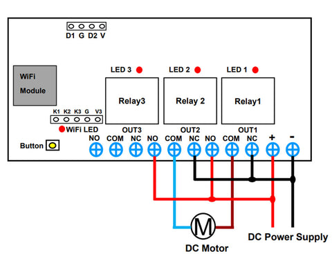
1) Connect the positive pole of the DC power supply to the input terminal "+" of WiFi switch, and connect the negative pole of the DC power supply to the input terminal "-" of WiFi switch;
2) Connect the positive pole of the DC power to two terminals "NO" of WiFi switch "OUT1" and "OUT2", connect the negative pole of the DC power supply to two terminals "NC" of WiFi switch "OUT1" and "OUT2";
3) Connect two wires of DC motor or linear actuator to two terminals "COM" of WiFi switch "OUT1" and "OUT2", you can change these two wires to change the working direction of the linear actuator or motor.
2. Operation:
1) Press button 1 on the APP, relay 1 is activated (two terminals "NO" and "COM" of OUT1 are connected, two terminals "NC" and "COM" are disconnected), and DC motor rotates in the positive direction, or linear actuator extends.
2) Press button 1 on the APP again, relay 1 is deactivated (two terminals "OUT" and "COM" of OUT1 are disconnected, two terminals "NC" and "COM" are connected), DC motor or linear actuator stops working.
3) Press button 2 on the APP, relay 2 is activated (two terminals "NO" and "COM" of OUT2 are connected, two terminals "NC" and "COM" are disconnected), and DC motor rotates in the reverse direction, or linear actuator retracts.
4) Press button 2 on the APP again, relay 2 is deactivated (two terminals "OUT" and "COM" of OUT2 are disconnected, two terminals "NC" and "COM" are connected), DC motor or linear actuator stops working.
C. Control small bi-directional AC motor (three control lines):
1. Connect as shown below: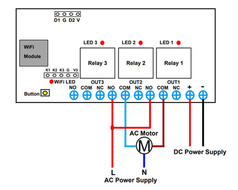
1) Connect the positive pole of the DC power supply to the input terminal "+" of the WiFi switch, and connect the negative pole of the DC power supply to the input terminal "-" of the WiFi switch;
2) Connect the live wire of the AC power supply to two terminals "NO" of the WiFi switch"OUT1" and "OUT2", and connect the neutral wire of the AC power supply to the common terminal of the AC motor;
3) Connect the forward and reverse connection wires of the AC motor to two terminals “COM” of the WiFi switch “OUT1” and “OUT2” respectively, you can change these two wires to change the working direction of the motor.
2. Operation:
1) Press button 1 on the APP, relay 1 is activated (two terminals "NO" and "COM" of OUT1 are connected, two terminals "NC" and "COM" are disconnected), and AC motor rotates in the positive direction.
2) Press button 1 on the APP again, relay 1 is deactivated (two terminals "NO" and "COM" of OUT1 are disconnected, two terminals "NC" and "COM" are connected), and AC motor stops working.
3) Press button 2 on the APP, relay 2 is activated (two terminals "NO" and "COM" of OUT2 are connected, two terminals "NC" and "COM" are disconnected), and AC motor rotates in the reverse direction.
4) Press button 2 on the APP again, relay 2 is deactivated (two terminals "NO" and "COM" of OUT2 are disconnected, two terminals "NC" and "COM" are connected), and AC motor stops working.
D. The use of third relay:
1. The thirdrelay works in self-lockingmode, and the operation is as follows:
Press button 3 on the APP, the third relay is activated (two terminals "NO" and "COM" of OUT3 are connected, two terminals "NC" and "COM" are disconnected); press button 3on the APP again, the thirdrelay is deactivated (two terminals "NO" and "COM" of OUT3 are disconnected, and two terminals "NC" and "COM" are connected).
2.When using the third relay to control a DC lamp, connect as shown below: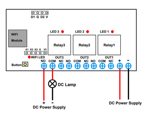
1) Connect the positive pole of the DC power supply to the terminal "NO" of "OUT3", connect the terminal "COM" of "OUT3" to the positive pole of the DC lamp, and connect the negative pole of the DC lamp to the negative pole of the DC power supply.
2) Press button 3 on the APP, relay 3 is activated (two terminals "NO" and "COM" of OUT3 are connected, two terminals "NC" and "COM" are disconnected), and the DC lamp is turned on.
3) Press button 3 on the APP again, relay 3 is deactivated (two terminals "NO" and "COM" of OUT3 are disconnected, two terminals "NC" and "COM" are connected), and the DC lamp is turned off.
3.When using a third relayto control an AC lamp, connect as shown below: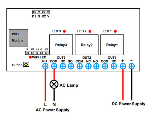
1) Connect the live wire of AC power supply to the terminal "NO" of "OUT3", connect the terminal "COM" of "OUT3" to one side of the AC lamp, and connect another side of AC lamp to the neutral wire of the AC power supply.
2) Press button 3 on the APP, relay 3 is activated (two terminals "NO" and "COM" of OUT3 are connected, two terminals "NC" and "COM" are disconnected), and the AC lamp is turned on.
3) Press button 3 on the APP again, relay 3 is deactivated (two terminals "NO" and "COM" of OUT3 are disconnected, two terminals "NC" and "COM" are connected), and the AC lamp is turned off.
E. Manual Function:
Connect a three-pin manual switch to terminals "K1", "K2" and "G".
When use the manual switch to connect the terminals "K1" and "G", the relay 1 is activated, and the motor rotates in the positive direction.
When use the manual switch to disconnect the terminals "K1" and "G", relay 1 is deactivated, and the motor stops working.
When use the manual switch to connect the terminals "K2" and "G", the relay 2 is activated, and the motor rotates in the reverse direction.
When use the manual switch to disconnect the terminals "K2" and "G", the relay 2 is deactivated, and the motor stops working.
You can also connect a two-pin manual switch to the terminals "K3" and "G".
When use the manual switch to connect the terminals "K3" and "G", the relay 3 is activated, and the lamp is turned on.
When use the manual switch to disconnect the terminals "K3" and "G", the relay 3 is deactivated, and the lamp is turned off.
F. Limit Function:
1. Connect normally open limit switches:
Connect two normally open limit switches to two sets of terminals “G” and “D”respectively, connect as shown below: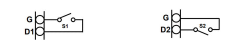
When the motor rotates in the positive direction, if the limit switch S1 is triggered, the motor will automatically stop. When the motor rotates in the reverse direction, if the limit switch S2 is triggered, the motor will automatically stop.
2. Connect the sensors, such as Photoelectric switch, Proximity switch or Hall switch:
Connect the positive pole, negative pole and signal wire from two sensor switches to two sets of terminals “V”, “G” and “D” respectively, connect as shown below: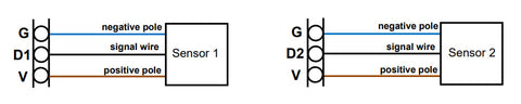
When the motor rotates in the positive direction, if the sensor 1 is triggered, the motor will automatically stop. When the motor rotates in the reverse direction, if the sensor 2 is triggered, the motor will automatically stop.